|
||||||||||
|
|
||||||||||
|
||||||||||
|
|
||||||||||
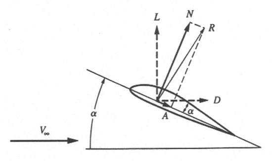
This figure shows how the forces of lift and drag act on a two-dimensional airfoil. The airfoil shape is traveling at a velocity of V∞ and meets the incoming airflow at an angle of attack of α. The lift force is defined as being perpendicular to the velocity vector while drag is defined as being parallel to it. No matter what the angle of attack is, lift and drag will always maintain this same orientation to the velocity.
However, the diagram also introduces two new variables called N for normal force and A for axial force. These two quantities are not measured with respect to the velocity, but with respect to the geometry of the airfoil itself. In the case of a 2D airfoil like that shown here, the key geometrical parameter is the chord line. The chord line is defined as a straight line from the leading edge to the trailing edge of the airfoil. Similar to lift and drag, normal force and axial force are defined as being perpendicular and parallel to the chord line, respectively.
We have already seen that lift and drag always keep the same orientation with respect to the velocity no matter what the angle of attack is. However, the orientation between these two forces and the chord line of the airfoil does change. The reverse is true for the normal and axial forces. As angle of attack changes, the normal and axial forces change orientation with respect to the velocity, but the two vectors always maintain the same orientation with respect to the body.
That brings us to the equations you mention. The quantities lift, drag, normal force, and axial force are all related by simple trigonometry. If we know the values in one reference system, we can easily convert to the other system using the following equations.
If you know normal force (N) and axial force (A), calculate lift (L) and drag (D):
If you know lift (L) and drag (D), calculate normal force (N) and axial force (A):
Up until now, we have only talked about the actual forces L, D, N, and A. These quantities would be measured in force units like pounds or newtons. However, we have seen in previous discussions that engineers often convert these forces into nondimensional coefficients, like CL for lift and CD for drag, to make comparisons more easily. Similar coefficients also exist for the normal force (CN) and axial force (CA). We will continue to use these coefficients for the remainder of this article for reasons that will become obvious shortly.
As described above, the equations you discovered are indeed correct, yet the answers you calculated when applying them are not. The error in your simple analysis is that you assumed values for N and A that are constant with angle of attack. In actuality, these values will vary similarly to how L and D change with α. You applied the mathematics of the equations properly but assumed faulty inputs for the variables. We need a more realistic example to better demonstrate the relationships between these two sets of aerodynamic forces.
Instead of making up numbers, we can use an example provided in a previous article about the aerodynamic behavior of airfoils at high angle of attack. In that answer, we introduced two graphs showing how the lift and drag coefficients for a typical 2D airfoil change over angles of attack from 0° to 180°. Several of the values provided in these graphs have been extracted and are listed in the table below. The table also shows the corresponding normal and axial force coefficients converted using the equations provided earlier. You can use these values yourself to convert back and forth and make sure you understand how all four variables are calculated.
Alpha Lift (CL) Drag (CD) Normal (CN) Axial (CA) [deg] [-] [-] [-] [-] ==================================================== 0 0.0000 0.0000 0.0000 0.0000 10 0.8628 0.0209 0.8533 -0.1293 15 1.0314 0.0577 1.0112 -0.2112 17 0.5802 0.2164 0.6181 0.0373 23 0.5752 0.3378 0.6615 0.0862 33 0.8826 0.6971 1.1199 0.1039 45 0.9620 1.0828 1.4459 0.0854 55 0.8579 1.4210 1.6561 0.1123 70 0.5603 1.6585 1.7501 0.0407 80 0.3273 1.8010 1.8305 -0.0096 90 0.0744 1.8377 1.8377 -0.0744 100 -0.1835 1.7581 1.7632 -0.1246 110 -0.4265 1.6362 1.6834 -0.1589 120 -0.6298 1.5037 1.6171 -0.2065 130 -0.8132 1.2601 1.4880 -0.1870 140 -0.8975 0.9425 1.2934 -0.1451 150 -0.7041 0.6038 0.9117 -0.1708 160 -0.5802 0.3126 0.6521 -0.0953 170 -0.8132 0.1325 0.8239 0.0107 180 0.0000 0.0000 0.0000 0.0000 |
Note the trends in these graphs. For example, lift and normal force are nearly identical for small angles near 0° but then grow quite different. Normal force reaches a maximum at 90° but lift is zero. Meanwhile, drag also reaches a maximum at 90° but axial force is zero. This behavior makes sense physically because at 90°, the chord line is perpendicular to the velocity. In other words, the two reference systems are aligned such that the normal force and drag force lie on top of each other. Furthermore, the airfoil is nothing more than a flat plate at this extreme angle so that it creates no lift (or axial force) but generates the greatest drag (and normal force) possible. Mathematically, we should expect this situation based on the behavior of the sine and cosine functions in the conversion equations discussed earlier.
One final question you may be wondering is why one would want to use normal and axial force versus lift and drag in the first place. That discussion takes us back to the earliest days of aviation. One of the pioneers of aerodynamics was Otto Lilienthal of Germany. Lilienthal was one of the first to conduct experiments to measure the forces generated by different kinds of wings and airfoil shapes. He published his findings in 1889 under the title Der Vogelflug als Grundlage der Fliegekunst, or Bird Flight as the Basis of Aviation. The convention Lilienthal used in taking his measurements was based on the geometry of the body, so he used normal force and axial force.
The Wright brothers in America made great use of Lilienthal's work in designing their early gliders. However, the Wrights preferred to use the quantities lift and drag since these values were easier to measure in a wind tunnel. The brothers proceeded to convert Lilienthal's normal and axial force tables to lift and drag tables using the same equations explained above. However, the Wrights eventually threw out Lilienthal's work anyway because they had misinterpreted his results. Luckily, the Wright's measurements using their wind tunnel proved to be just as accurate and became instrumental in the development of the Wright Flyer.
Most engineers continue to use lift and drag today since this system is better suited to the configuration of a
normal airplane. However, normal and axial force are typically preferred over lift and drag for symmetric bodies
of revolution like missiles, bombs, and rockets.
- answer by Jeff Scott, 19 September 2004
Related Topics:
Read More Articles:


|
Aircraft | Design | Ask Us | Shop | Search |
|
|
| About Us | Contact Us | Copyright © 1997- | |||
|
|
|||
