|
||||||||||
|
|
||||||||||
|
||||||||||
|
|
||||||||||
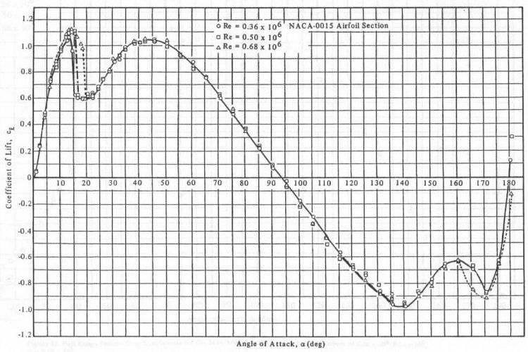
You'll notice that both coefficients behave much like a flat plate. In fact, beyond the stall angle, all airfoils behave in essentially the same manner as a flat plate. Since the flow becomes separated and the boundary layer is very thick, the actual shape of the airfoil has little or no effect on its aerodynamics in the stalled region. Flat plate aerodynamics predict that the lift coefficient reaches a maximum of 1.2 at 45° before decreasing to 0 at 90°. It is therefore not surprising that the lift curve shown above also indicates a peak of nearly 1.2 at 45° and decreases to 0 close to 90°.

As for drag, a two-dimensional flat plate at an angle of 90° to the airflow has a cd of about 2. Since an airfoil section is also a 2D surface, it is not surprising that the cd vs. alpha also reaches a peak of nearly 2 at 90°.
You can apply these same trends to any airfoil. Most airfoils stall in the region of 15° to 20°. Between 20° and 25°, the cl begins increasing again to a peak of 1.2 at 45°. The lift then decreases in an approximately linear fashion to 0 at 90°. The trend from 90° to 180° is exactly the same except the cl is negative. Drag behaves much like a bell curve, with a peak of 2 at 90° while the coefficient is close to 0 at 0° and 180°.
The experimental data shown above is from Sandia National Labs report SAND80-2114 where additional information on
this subject can also be found. The report is entitled "Aerodynamic Characteristics of Seven Symmetrical Airfoil
Sections Through 180-Degree Angle of Attack For Use In Aerodynamic Analysis of Vertical Axis Wind Turbines" by R.E.
Sheldahl and P.C. Klimas. This report can be downloaded at the
Sandia Wind Energy Technology site.
- answer by Jeff Scott, 16 November 2003
Related Topics:
Read More Articles:


|
Aircraft | Design | Ask Us | Shop | Search |
|
|
| About Us | Contact Us | Copyright © 1997- | |||
|
|
|||
