|
||||||||||
|
|
||||||||||
|
||||||||||
|
|
||||||||||
|
|
|
||||||||||||||
|
Having introduced the three principal families of nozzle shapes, we will now look more
closely at the two major subclasses of annular, or plug, nozzles.
Radial Out-Flow Nozzles:Two major types of plug nozzles have been developed to date. They are distinguished by the method in which they expand the exhaust, outward or inward. The radial out-flow nozzle was the subject of much research in the late 1960s and early 1970s. Examples of this type are the expansion-deflection (E-D), reverse-flow (R-F), and horizontal-flow (H-F) nozzles shown in the figure below.

Size comparison of optimal cone, bell, and radial nozzles for a given set of conditions [from Huzel and Huang, 1967]The name of each of these nozzles indicates how it functions. The expansion-deflection nozzle works much like a bell nozzle since the exhaust gases are forced into a converging throat region of low area before expanding in a bell-shaped nozzle. However, the flow is deflected by a plug, or centerbody, that forces the gases away from the center of the nozzle. Thus, the E-D is a radial out-flow nozzle. The reverse-flow nozzle gets its name because the fuel is injected from underneath, but the exhaust gases are rotated 180° thereby reversing their direction. Similarly, the fuel in the horizontal-flow nozzle is injected sideways, but the exhaust is rotated 90°. Judging by the amount of literature obtained on this subject, little work has been done on the R-F and H-F nozzles, and they will not be considered further. The E-D, on the other hand, has been one of the most studied forms of annular nozzles. While similar in nature to the bell nozzle, the most notable difference is the addition of a centerbody. As shown below, this "plug" may be located upstream of, downstream of, or in the throat, with each location resulting in better performance for a given set of operating conditions.
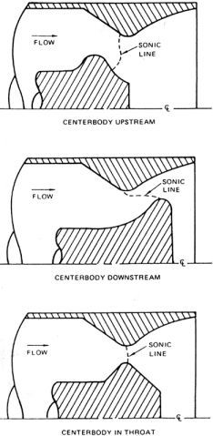
Comparison of centerbody locations in Expansion-Deflection nozzles [from Conley et al, 1984]The purpose of the centerbody is to force the flow to remain attached to, or to stick to, the nozzle walls, as illustrated in the following figure.
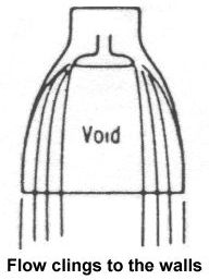
Expansion-deflection nozzle flow behavior at low altitude [from Sutton, 1992]This behavior is desirable at low altitudes because the atmospheric pressure is high and may be greater than the pressure of the exhaust gases. When this occurs, the exhaust is forced inward and no longer exerts force on the nozzle walls, so thrust is decreased and the rocket becomes less efficient. The centerbody, however, increases the pressure of the exhaust gases by squeezing the gases into a smaller area thereby virtually eliminating any loss in thrust at low altitude. |


|
Aircraft | Design | Ask Us | Shop | Search |
|
|
| About Us | Contact Us | Copyright © 1997- | |||
|
|
|||
