|
||||||||||
|
|
||||||||||
|
||||||||||
|
|
||||||||||
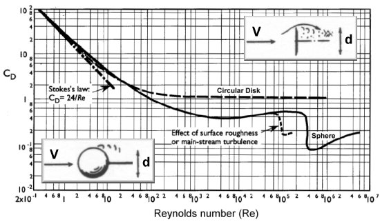
It sounds like the shape you have is not a flat disk but a cylinder. Estimates for the drag coefficient of a cylinder oriented so that the blunt end is perpendicular to the flow can be found in the classic book Fluid Dynamic Drag by Dr. Sighard Hoerner. According to the following graph, the coefficient of drag for a cylinder in this orientation is about 0.81 so long as the l/d (length-to-diameter ratio or fineness ratio) is greater than 2. As the fineness ratio shrinks to zero, the cylinder collapses to a flat circular disk. It is therefore not surprising that the drag coefficient for a cylinder with l/d=0 is about 1.17, the same as a flat disk. The reference area for a cylinder is also the same as that used for the disk except the radius is that of the cylinder's circular cross-section.
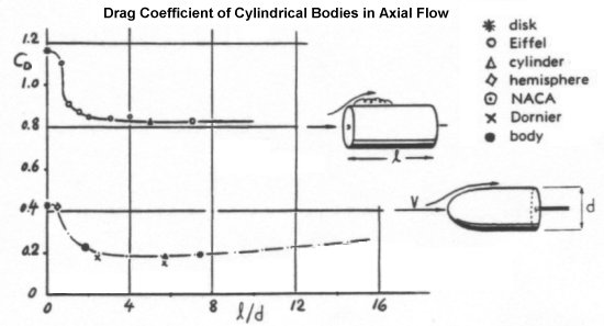
The drag coefficient for a cone pointed into the airflow is a bit more complex since it depends on the cone's shape. In particular, the drag will vary depending on how steep the angle of the cone is. The angle of interest is called the half-vertex angle, ε, measured from the centerline of the cone to one of its walls. The larger this angle becomes, the higher the drag of the cone is.

Based on the above graph provided by Hoerner, it appears that the drag coefficient is nearly linear with the half-vertex angle from 0° up to 90°. We can use this information to derive the following equation that closely approximates the experimental data for drag coefficient versus the half-vertex angle of the cone. Simply use the appropriate angle (in degrees) for the cone in your wind tunnel experiment to calculate the drag coefficient.
A half-vertex angle of 90° causes the cone to turn into a flat circular disk. As we have already seen, the drag
coefficient of this shape is about 1.17. Plugging 90° into the above equation results in a drag coefficient of
1.17, exactly what we should expect at this particular angle. Again, the reference area for a cone is equal to the
cross-sectional area of its base and can be calculated as
Above 90°, the cone folds backwards and becomes hollow like a cup. The drag of this cupped shape remains fairly constant as the half-vertex angle of this cone increases to 180°. Typical drag coefficients of these and other basic shapes at Reynolds numbers between 10,000 and 1 million are compared in the following diagram.
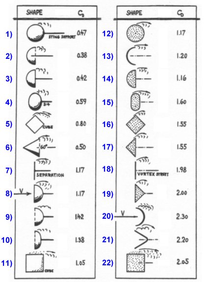
The table on the left compares three-dimensional shapes like disks, cones, and spheres while the table on the right is for two-dimensional shapes like plates, wedges, and cylinders. On the 3D side, note the flat circular disk in shape #7. The drag coefficient for this shape is given as 1.17, as we have discussed. The shape just above this one is a 60° cone, or a cone with a half-vertex angle of 30°. The drag coefficient of this shape is listed as 0.5. The simple equation we derived earlier predicts 0.498, a very close approximation.
Also note the two-dimensional cylinder in shape #12. This cylinder is oriented with its axis perpendicular to the flow rather than into the flow as described earlier. If a cylinder is mounted in this orientation in a wind tunnel, the drag coefficient should be about 1.17 using the same circular reference area assumed for all the shapes we have discussed.
This explanation has probably gone into much greater detail than was required, but understanding the drag
characteristics of these simple shapes can often be very useful in predicting how more complicated objects behave.
We have also explained the similarities between these different shapes, such as how they all collapse into flat
disks and produce the same drag. Simple rules of thumb like these are often very useful as a method of quickly
evaluating the accuracy of experimental data compared to theoretical predictions. Judgment skills of this kind
can prove indispensable in the day-to-day work of an engineer.
- answer by Jeff Scott, 5 June 2005
Related Topics:
Read More Articles:


|
Aircraft | Design | Ask Us | Shop | Search |
|
|
| About Us | Contact Us | Copyright © 1997- | |||
|
|
|||
