|
||||||||||
|
|
||||||||||
|
||||||||||
|
|
||||||||||
|
|
|
||||||||||||||||||||||||||||||||||||||||||||||
|
Maneuver Envelope:The maximum loadings anticipated during a typical mission of the Storm Shadow are represented in the velocity-load (V-n) diagram shown below.
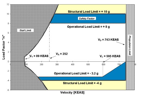
Velocity-load diagramWhile this maneuver envelope is similar to that of a small military attack aircraft, the stringent requirements called for in the RFP dictate larger load limits than might otherwise be expected. The most important value shown on the V-n diagram is the operational load limit of +8g chosen to satisfy performance requirements. An additional 25% safety factor has been added corresponding to a +10g structural limit, beyond which the aircraft will suffer damage and failure.
Wing Loading:The forces acting on the aircraft include structural weight, fuel weight, and point loads (e.g. bomb, engine, and landing gear).
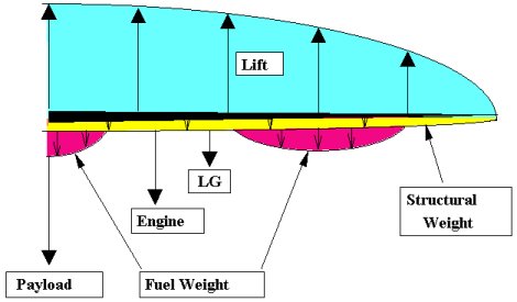
Loads acting along half of wingEach of these loads and the combined load during 1g flight along half of the wingspan are illustrated below.
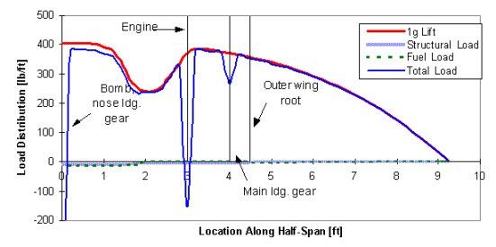
Load distribution vs. half-span locationFrom this data, the maximum shear, bending moment, and torsion acting on the wing were computed and used to design the aircraft structure.
Sturctural Design:The wing spars counteract the majority of the load acting on the wing. The spar design was optimized to withstand the maximum load on the wing while minimizing the overall structural weight. The optimum arrangement was found to be three spars: one located at 45% chord, or the point of maximum thickness, since this location best counteracts the stress on the spar, and others at 15% and 60% chord to provide attachments for control surfaces. Ribs are also used to join the spars and reduce wing twist. The fuselage uses a series of ring-framed bulkheads to maintain the fuselage shape and to support point loads like the engines and landing gear. The three center bulkheads serve as the wing carry-through structure through which the loads on the wings are transmitted. A series of four longerons run the length of the aircraft adding longitudinal stiffness. The aircraft skin was designed to resist the torsion which tends to twist the aircraft. The structural arrangement of the aircraft is illustrated below.
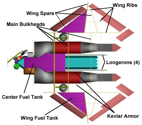
Storm Shadow structural arrangement
Material Selection:The wing spars are composed of a high strength unidirectional graphite/epoxy composite material chosen for its high strength and low weight. The fuselage bulkheads are made of a high strength aluminum alloy. This arrangement was chosen through a trade study to determine the optimum balance between overall structural weight and cost. Because of its stealth and torsional strength characteristics, a high modulus graphite/epoxy was also selected for the aircraft skin. A further use of advanced composites is the placement of 1/2-inch Kevlar armor around the engines. This was done to improve survivability since the aircraft spends much of its time at low levels where critical systems must be protected from battle damage. The usage of materials on the aircraft are summarized in the following table and weight distribution graph.
Material Selection
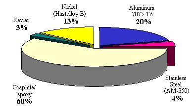
Material breakdown by weightLanding Gear:The aircraft uses a tricycle landing gear arrangement. As shown below, each gear strut is attached to a bulkhead while the drag strut (which provides extra rigidity) is attached to the gear boxes (not shown for clarity) containing the gear. The nose gear retracts backward and rotates to lie parallel to the aircraft leading edge. The main gear retract forward, and as they do so, the strut uses a spiral retraction mechanism to rotate the wheel flush with the aircraft skin. The gear also fold just below the oleo shock absorber to fit between the bulkheads. As each gear retracts, the telescoping drag brace shortens while its end slides down the strut allowing the brace to stow alongside. Though the retraction mechanisms are complex, they are required by the limited space available within the aircraft.
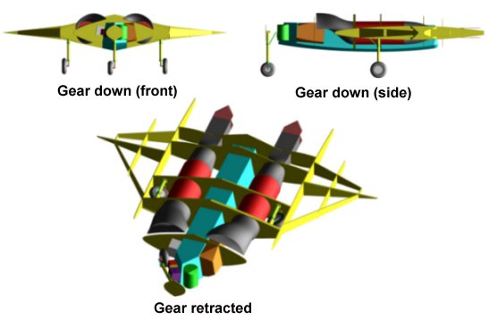
Landing gear geometry |


|
Aircraft | Design | Ask Us | Shop | Search |
|
|
| About Us | Contact Us | Copyright © 1997- | |||
|
|
|||
