|
||||||||||
|
|
||||||||||
|
||||||||||
|
|
||||||||||
|
|
|
||||||||||||||||||||||||||||||||||||||||||||||||||||||||||||||||||||||||||||||||||||||||||||||||||
|
Wing Design:As already discussed, the aero-diamond shape was selected because of its inherent stealth characteristics and because it would minimize the shift in center of gravity due to payload release. The basic aero-diamond shape was modified by adding saw-tooths along the trailing edge to provide locations for additional control surfaces. Since the aero-diamond is defined as a planform on which the leading egde is parallel to the opposite trailing edge, the geometry of the planform was derived from the leading edge (LE) sweep angle, the fuselage length, and the distance between the saw-tooths. An initial LE angle of 48° was selected since it is similar to that used on the wing of the F-22 fighter. However, the wing design was later optimized to reduce drag during the Mach 0.9 ingress/egress segments. As shown below, the drag (expressed as thrust required) decreases dramatically as the sweep angle increases for the ingress case while it remains roughly constant for the cruise case. A LE angle of 55° allowed just enough internal space for structures, payload, fuel, and avionics while minimizing drag and allowing the aircraft to better fit within the C-5 transport.
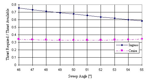
Percent thrust required vs. leading edge angleThe overall length of the aircraft was dictated by the bomb bay dimensions. An airfoil shape was fitted around the bay resulting in a total length of 20 ft. Since the engine nozzles are located within the triangular cutouts, the distance between them is dictated by the diameter of the engines and bomb bay width. Both the aerodynamic and structural design proceeded from treating the wing as being composed of an inboard wing (the fuselage) and an outboard wing, as indicated by the dashed lines in the figure below. Key characteristics of the wing are summarized in the table below.
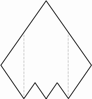
Storm Shadow planform
Storm Shadow Wing Geometry
Airfoil Selection:Since the Storm Shadow is a flying wing, the proper selection of an airfoil was crucial to the success of the design. Since a flying wing typically does not have a horizontal tail to counteract pitching moments, the airfoil itself must have a low pitching moment. A second key factor in selecting an airfoil was a high critical Mach number (Mcr) to minimize shock drag. Thus, the airfoils used on both the inboard and outboard wings must have little camber to reduce pitching moment as well as a small thickness to chord ratio (t/c) and leading edge radius to ensure a high Mcr. The airfoils must also be thick enough to provide a sufficient internal volume. The airfoils selected as possible candidates are listed below.
Airfoil Characteristics
The NACA 66-008 was chosen for the outboard wing because (a) its critical Mach number is less than the maximum Mach number specified by the RFP and (b) its maximum thickness is closer to the middle which better suits the structural design. The NACA 67,1-015 was selected for the inboard wing because the bomb bay fits better within its shape. Lift and Drag Characteristics:Since the aero-diamond planform is relatively new, very little analytical processes for calculating the lift of such a shape have been developed. However, NASA has conducted wind tunnel tests on flat plates with planforms very similar to that of the Storm Shadow. Using these data, a more accurate estimation of the lift characteristics of the aircraft could be made. The resulting lift curves for the aircraft at various flight segments are shown below.
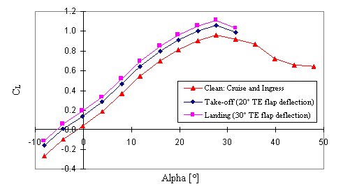
Lift curves for various flight segmentsA standard component drag buildup was also performed for the entire aircraft yielding the results shown in the following table. Drag polars are also presented.
Drag Breakdown for Fight Segments
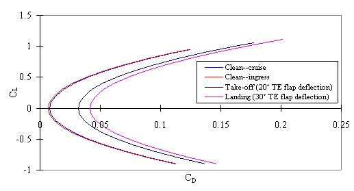
Drag polars for various flight segments |


|
Aircraft | Design | Ask Us | Shop | Search |
|
|
| About Us | Contact Us | Copyright © 1997- | |||
|
|
|||
