|
||||||||||
|
|
||||||||||
|
||||||||||
|
|
||||||||||
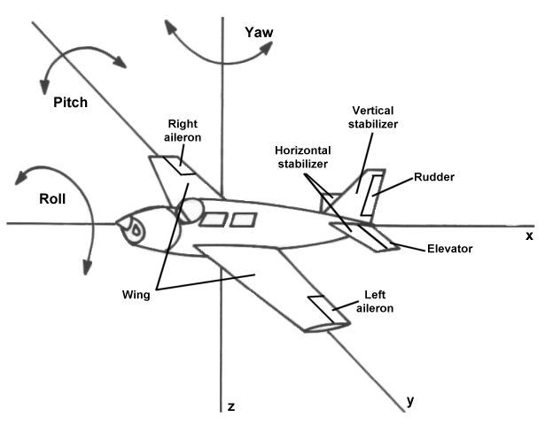
First of all, we have already referred to the aircraft bank angle, typically denoted by the Greek symbol φ (pronounced "fee"). The concept of the bank angle, or roll angle, was introduced in a previous article about the parts of an aircraft. In particular, the section about control surfaces discusses the three axes of motion about which an aircraft can rotate. Among these is roll, defined as a rotation about the x-axis, or longitudinal axis, of a flying vehicle.
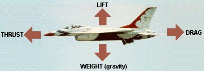
We have also previously discussed the four forces of flight, those being lift and weight that act in a vertical direction and thrust and drag in the horizontal direction. When an aircraft is flying straight and level and not accelerating, the lift generated by the plane is equal to its weight and the thrust generated by its engine is equal to drag.
However, the question you ask about is related to turning flight. In that case, the aircraft's flight path is no longer a straight line but now follows a curved path. In general, any condition in which the aircraft's lift is not equal to its weight will result in a curving flightpath, but the specific case you are asking about is the level turn illustrated below.
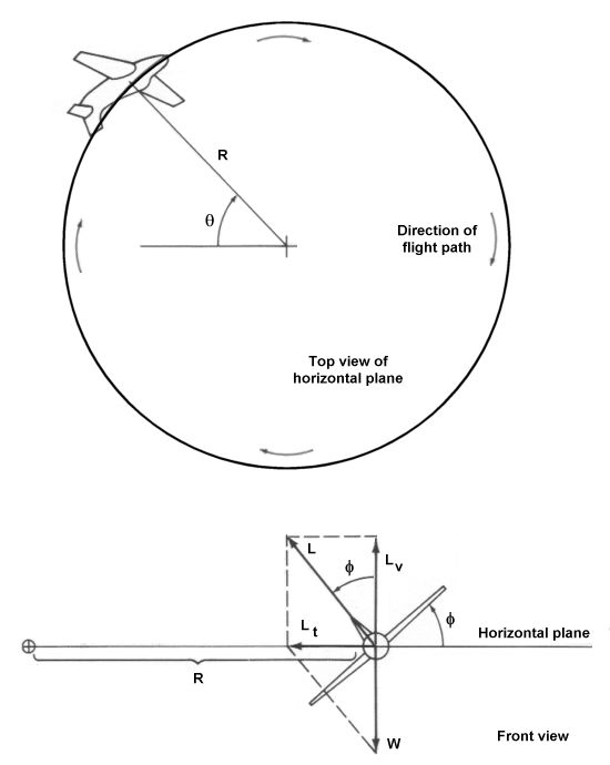
You will note in the front view of the aircraft that the plane is rolled away from the horizontal and vertical planes by the angle φ discussed earlier. The lift vector L acting on the aircraft is also rolled by that same angle such that it no longer directly opposes the plane's weight. Now observe the following diagram.
In both cases, the aircraft is rolled to the same bank angle. In the first case, however, the vertical component of lift is less than the weight. Because of this inequality, the greater force imparted by the weight will pull the aircraft downward and it does not maintain the same altitude. The pilot can overcome this behavior by pulling the stick back to increase the lift of the plane and maintain the same altitude. It is for this reason that we refer to the maneuver as a level turn, since the aircraft is banked into a turning motion but maintains the same altitude.
Since the aircraft is banked, we can break the total lift force L into two components. The vertical component of lift, Lv, opposes the aircraft weight, and since the aircraft maintains a constant altitude, those two forces must be equal. Simple trigonometry then tells us that
A second component of the total force vector acts in the horizontal plane. This force acts perpendicular to the flight path such that it causes the aircraft to turn in a circular path with a turn radius R. We will label this force the turning component of lift, Lt. We can calculate this force using the Pythagorean theorem.
Thus far, all we have talked about are the forces acting on an aircraft rolled into a turn, but how does "pulling g's" come into play? To understand that concept, we need to introduce a new variable called the load factor, n, defined as the ratio of lift acting on an aircraft divided by its weight.
The load factor describes how many g's act on an aircraft in any given maneuver. For example, a plane with a total lift five times greater than its weight experiences a load factor of 5 g's. In more physical terms, we often refer to the load factor as "apparent weight." In other words, a pilot pulling 5 g's feels like he weighs five times more than normal because of the additional force acting on his body.
Substituting the definition of load factor into the above equations gives us the following relationships:

![]()
The first of these equations is directly related to the question you've posed. If you plug in a value of 60°, you'll find that the load factor n is equal to 2. You'll also note that the variable of speed does not show up in this equation, only the bank angle. It is for this reason that the load factor is independent of velocity. Any aircraft in a level turn and pulling a given number of g's must maintain a constant bank angle independent of its speed or its weight.
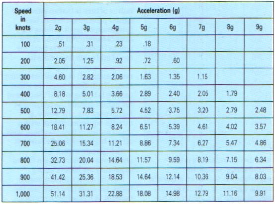
Where speed does come into play is in the radius of turn and turn rate, both of which can be derived from the relationship for the component of lift that turns the aircraft. However, we need an additional equation to introduce a velocity term. For any object traveling in a circular path at a radius r and a constant velocity v, the radial acceleration a is given by the equation:
In the case of our level turn, the velocity is the freestream velocity at which the aircraft is traveling, V∞ and the radius of the circular flight path is R. Newton's second law of motion tells us that a force is the product of the acceleration on an object and its mass. Substituting these terms then gives us a second relationship for the turning component of lift.
Setting both equations for Lt equal to each other, we can solve for the turn radius R:
For any body traveling in a circular path, the turn rate ω (pronounced "omega") is given by dividing the velocity by the radius of the circle. Substituting the above equation yields the following relationship.
These last two equations tell us two very important properties about how to maximize the performance of an aircraft in maneuvering flight. Military fighters, in particular, need to be able to turn in as short a time and distance as possible. It is therefore desirable that the turn radius R be minimized and the rate of turn ω be maximized. The two equations shown above tell us that in order to obtain both parameters at once, an aircraft must be designed to turn at
To sum up this discussion, let's review the following two figures. The first graphically illustrates the effect of g and bank angle on the flight of an aircraft.
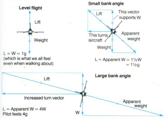
In steady, level flight, the lift and weight are equal, and the aircraft experiences a load factor of 1g. When turning, an additional sideways motion is imparted on the plane. To hold the turn at a constant altitude, the plane must be banked to an angle at which the total lift supports both the weight of the plane and the pull of the turn. This increase in lift is felt as an increase in the apparent weight of the aircraft, and it is said to be "pulling g's." The tighter the turn becomes, the greater the force into the turn becomes, the greater the bank angle must be, and the higher the apparent weight feels.
The bank angle itself is directly related to the load factor. For any given load factor, there exists one specific bank angle. We can solve for that angle by rearranging one of our earlier equations to the form:
The resulting bank angles required to maintain a level turn at a given load factor are illustrated below.
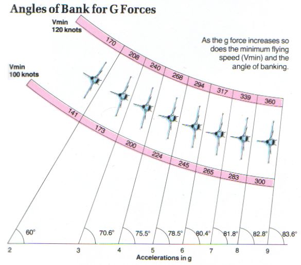
Furthermore, the above diagram illustrates that the minimum flying speed Vmin increases as load factor increases. A plane with a minimum airspeed of 120 knots in 1g flight must maintain at least 360 knots when flying at 9g. We can solve for the minimum flying speed using a previously derived equation for stall speed. Stall speed dictates the slowest possible speed at which an aircraft can generate just enough lift to remain airborne. The stall speed Vs in straight and level flight can be calculated based upon the lift equation once rearranged to the following form:
In banking flight, however, we have already established that

Combining these two equations tells us that the stall speed in banked flight, Vsb becomes:
The ratio of Vsb/Vs is plotted in the following graph. Note that the stall speed, or minimum flying speed, begins to increase rapidly beyond a bank angle of 60° which corresponds to 2 g's. As the bank angle approaches 90°, the minimum flying speed approaches infinity.
Finally, recall that at the beginning of this article, it was mentioned that the level turn is only one method of
achieving high-g turning flight. What makes the level turn unique is the fact that the altitude remains a constant
throughout the maneuver. In other words, the level turn is purely in a horizontal plane. An aircraft can also
generate similar performance by flying maneuvers in which the altitude changes. Examples include the symmetric
pull-up and the split-s, both of which are purely in a vertical plane. We will discuss these cases as well as
other common aerobatic and combat maneuvers in future installments.
- answer by Jeff Scott, 19 October 2003
Read More Articles:


|
Aircraft | Design | Ask Us | Shop | Search |
|
|
| About Us | Contact Us | Copyright © 1997- | |||
|
|
|||
