|
||||||||||
|
|
||||||||||
|
||||||||||
|
|
||||||||||
This series of airfoils was created at Gottingen University in Germany in the early days of aviation. I haven't found many references describing them in detail, but most of them were created during the 1920s and 1930s and some may date back into at least the 1910s.
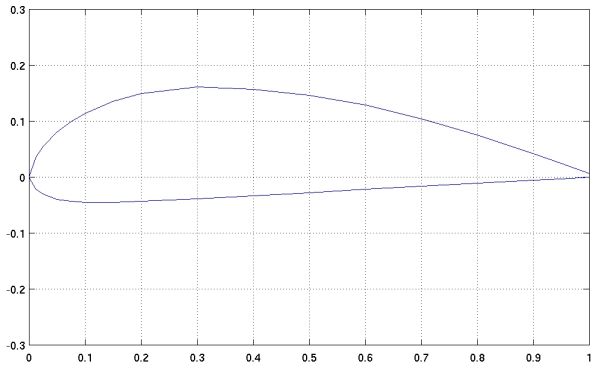
In any event, the number associated with each airfoil appears to have nothing to do with its geometry or performance. As far as I've been able to tell, the numbers are merely sequential, going from Gottingen 1 to at least Gottingen 804. As a new shape was created, it was merely given the next number available. Diagrams illustrating the shapes of the two airfoils you ask about are illustrated below. Note how dissimilar the two are despite their nearly identical names.
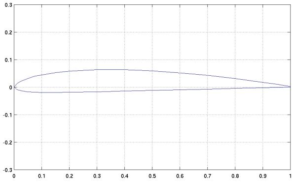
The Gottingen 622 shown above is only 8% thick with 2.4% camber while the 625 pictured below is 20% thick with 6% camber.
You ask for equations to calculate the coordinates for these shapes, but there are none. The NACA series was the first, and I believe only series of airfoils that was derived using systematic equations. The Gottingen and other early airfoils were designed purely by guessing shapes that might work well. You can read more about this practice in questions about the origins of NACA 4-digit airfoil equations and airfoil design practices.
Since it is not possible to mathematically generate the coordinates for these airfoils, you simply have to find the actual coordinates themselves. Coordinates for these and many other Gottingen airfoils are available at the NASG Airfoil Database and the UIUC Airfoil Coordinate Database. The specific coordinates you ask about are available at these locations:
The other information you ask about is lift and drag coefficient measurements at different angles of attack for both airfoils. I have been unable to locate any experimental data for these shapes, but I suggest you try analyzing both in the airfoil aerodynamic prediction software XFOIL.XFOIL is a very powerful program for investigating airfoil performance. It takes a little time to learn how to use, but the directions are relatively straightforward. I hadn't used it for several years before answering this question, but I was able to relearn the commands in under an hour. Thanks to XFOIL, I was able to generate the following computational predictions of lift (Cl), drag (Cd), and pitching moment (Cm) for the Gottingen 622 and 625. I ran the code in viscous mode, to include boundary layer effects, and chose operating conditions of Mach 0.2 and a Reynolds number of 750,000. Results are provided below showing the coefficients versus angle of attack and in polar format.
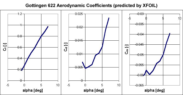
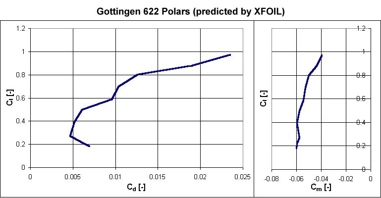
The Gottingen 622 proved difficult to analyze in XFOIL because of its relatively sharp nose. Thin airfoils with sharp noses are known for having very severe stall characteristics that produce a sharp and sudden decline in lift at the stall angle. Airfoils exhibiting this type of behavior are more difficult to analyze because XFOIL is often unable to converge on a solution in the vicinity of the stall angle of attack. I was unable to obtain coefficients at angles greater than 7° or less than -1°, so the airfoil probably stalls somewhere near these angles.
Somewhat more complete results were obtained for the Gottingen 625, as shown below.
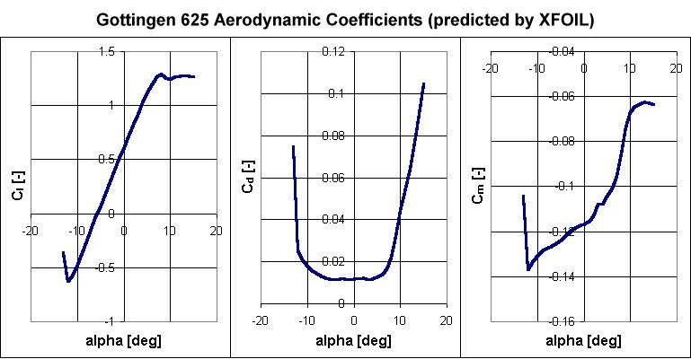
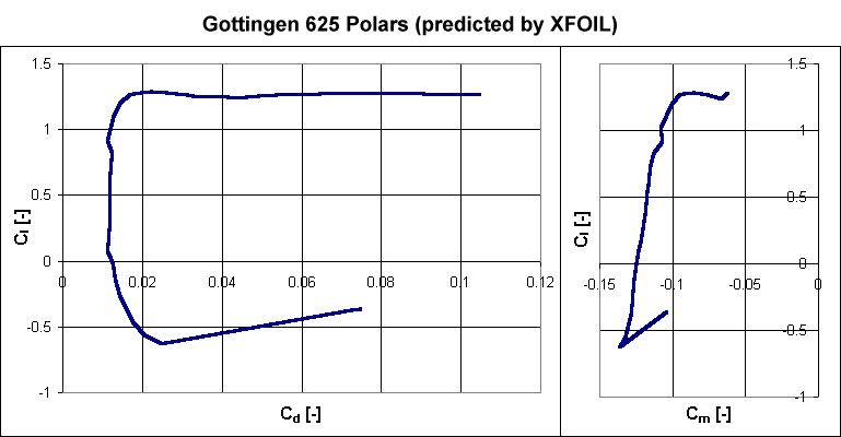
In contrast with the 622, the 625 is a thick airfoil with a much blunter, more rounded nose. Airfoils with these characteristics tend to exhibit benign stall characteristics since the stall behavior occurs more gradually over a range of angles of attack. That trend can be seen in the above graphs. Stall begins around 8°, but instead of dropping off suddenly, the lift remains relatively constant at higher angles. The stall was much sharper at negative angles of attack beyond -12°, but still appears to be more benign than seen on the Gottingen 622.
Bear in mind that these results are limited to a specific combination of Mach and Reynolds numbers, so results
may vary at different conditions. I encourage you to try out XFOIL yourself to see what kind of results you get.
- answer by Jeff Scott, 10 October 2004
Read More Articles:


|
Aircraft | Design | Ask Us | Shop | Search |
|
|
| About Us | Contact Us | Copyright © 1997- | |||
|
|
|||
