|
||||||||||
|
|
||||||||||
|
||||||||||
|
|
||||||||||
I'm currently trying to design a 3D model of the B-58
bomber, but I lack the mathematical definitions of NACA profiles such as 0003.46-64.069 (root section) and
0004.08-63 (tip section). I've found 4- and 5-digit NACA airfoil generators, but they don't seem to do the
job. Can you provide any help?
- question from Jean-Philippe Divo
This methodology began to change in the early 1930s with the publishing of a NACA report entitled The Characteristics of 78 Related Airfoil Sections from Tests in the Variable Density Wind Tunnel. In this landmark report, the authors noted that there were many similarities between the airfoils that were most successful, and the two primary variables that affect those shapes are the slope of the airfoil mean camber line and the thickness distribution above and below this line. They then presented a series of equations incorporating these two variables that could be used to generate an entire family of related airfoil shapes. As airfoil design became more sophisticated, this basic approach was modified to include additional variables, but these two basic geometrical values remained at the heart of all NACA airfoil series, as illustrated below.
NACA Four-Digit Series:
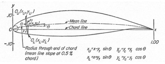
The first family of airfoils designed using this approach became known as the NACA Four-Digit Series. The first digit specifies the maximum camber (m) in percentage of the chord (airfoil length), the second indicates the position of the maximum camber (p) in tenths of chord, and the last two numbers provide the maximum thickness (t) of the airfoil in percentage of chord. For example, the NACA 2415 airfoil has a maximum thickness of 15% with a camber of 2% located 40% back from the airfoil leading edge (or 0.4c). Utilizing these m, p, and t values, we can compute the coordinates for an entire airfoil using the following relationships:
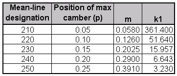
The NACA Five-Digit Series uses the same thickness forms as the Four-Digit Series but the mean camber line is defined differently and the naming convention is a bit more complex. The first digit, when multiplied by 3/2, yields the design lift coefficient (cl) in tenths. The next two digits, when divided by 2, give the position of the maximum camber (p) in tenths of chord. The final two digits again indicate the maximum thickness (t) in percentage of chord. For example, the NACA 23012 has a maximum thickness of 12%, a design lift coefficient of 0.3, and a maximum camber located 15% back from the leading edge. The steps needed to calculate the coordinates of such an airfoil are:
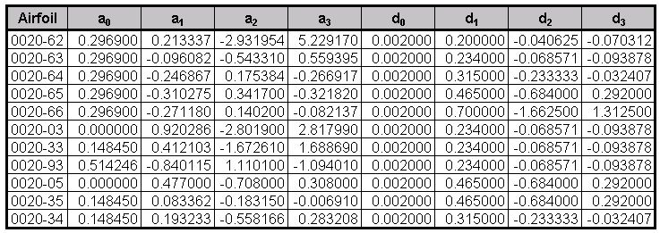
The airfoil sections you mention for the B-58 bomber are members of the Four-Digit Series, but the names are slightly different as these shapes have been modified. Let us consider the root section, the NACA 0003.46-64.069, as an example. The basic shape is the 0003, a 3% thick airfoil with 0% camber. This shape is a symmetrical airfoil that is identical above and below the mean camber line. The first modification we will consider is the 0003-64. The first digit following the dash refers to the roundedness of the nose. A value of 6 indicates that the nose radius is the same as the original airfoil while a value of 0 indicates a sharp leading edge. Increasing this value specifies an increasingly more rounded nose. The second digit determines the location of maximum thickness in tenths of chord. The default location for all four- and five-digit airfoils is 30% back from the leading edge. In this example, the location of maximum thickness has been moved back to 40% chord. Finally, notice that the 0003.46-64.069 features two sets of digits preceeded by decimals. These merely indicate slight adjustments to the maximum thickness and location thereof. Instead of being 3% thick, this airfoil is 3.46% thick. Instead of the maximum thickness being located at 40% chord, the position on this airfoil is at 40.69% chord. To compute the coordinates for a modified airfoil shape:
Unlike those airfoil families discussed so far, the 1-Series was developed based on airfoil theory rather than on geometrical relationships. By the time these airfoils were designed during the late 1930s, many advances had been made in inverse airfoil design methods. The basic concept behind this design approach is to specify the desired pressure distribution over the airfoil (this distribution dictates the lift characteristics of the shape) and then derive the geometrical shape that produces this pressure distribution. As a result, these airfoils were not generated using some set of analytical expressions like the Four- or Five-Digit Series. The 1-Series airfoils are identified by five digits, as exemplified by the NACA 16-212. The first digit, 1, indicates the series (this series was designed for airfoils with regions of barely supersonic flow). The 6 specifies the location of minimum pressure in tenths of chord, i.e. 60% back from the leading edge in this case. Following a dash, the first digit indicates the design lift coefficient in tenths (0.2) and the final two digits specify the maximum thickness in tenths of chord (12%). Since the 16-XXX airfoils are the only ones that have ever seen much use, this family is often referred to as the 16-Series rather than as a subset of the 1-Series.
NACA 6-Series:
Although NACA experimented with approximate theoretical methods that produced the 2-Series through the 5-Series, none of these approaches was found to accurately produce the desired airfoil behavior. The 6-Series was derived using an improved theoretical method that, like the 1-Series, relied on specifying the desired pressure distribution and employed advanced mathematics to derive the required geometrical shape. The goal of this approach was to design airfoils that maximized the region over which the airflow remains laminar. In so doing, the drag over a small range of lift coefficients can be substantially reduced. The naming convention of the 6-Series is by far the most confusing of any of the families discussed thus far, especially since many different variations exist. One of the more common examples is the NACA 641-212, a=0.6.
In this example, 6 denotes the series and indicates that this family is designed for greater laminar flow than the Four- or Five-Digit Series. The second digit, 4, is the location of the minimum pressure in tenths of chord (0.4c). The subscript 1 indicates that low drag is maintained at lift coefficients 0.1 above and below the design lift coefficient (0.2) specified by the first digit after the dash in tenths. The final two digits specify the thickness in percentage of chord, 12%. The fraction specified by a=___ indicates the percentage of the airfoil chord over which the pressure distribution on the airfoil is uniform, 60% chord in this case. If not specified, the quantity is assumed to be 1, or the distribution is constant over the entire airfoil.
NACA 7-Series:
The 7-Series was a further attempt to maximize the regions of laminar flow over an airfoil differentiating the locations of the minimum pressure on the upper and lower surfaces. An example is the NACA 747A315. The 7 denotes the series, the 4 provides the location of the minimum pressure on the upper surface in tenths of chord (40%), and the 7 provides the location of the minimum pressure on the lower surface in tenths of chord (70%). The fourth character, a letter, indicates the thickness distribution and mean line forms used. A series of standaradized forms derived from earlier families are designated by different letters. Again, the fifth digit incidates the design lift coefficient in tenths (0.3) and the final two integers are the airfoil thickness in perecentage of chord (15%).
NACA 8-Series:
A final variation on the 6- and 7-Series methodology was the NACA 8-Series designed for flight at supercritical speeds. Like the earlier airfoils, the goal was to maximize the extent of laminar flow on the upper and lower surfaces independently. The naming convention is very similar to the 7-Series, an example being the NACA 835A216. The 8 designates the series, 3 is the location of minimum pressure on the upper surface in tenths of chord (0.3c), 5 is the location of minimum pressure on the lower surface in tenths of chord (50%), the letter A distinguishes airfoils having different camber or thickness forms, 2 denotes the design lift coefficient in tenths (0.2), and 16 provides the airfoil thickness in percentage of chord (16%).
Further Sources:
This is probably the most theoretical and mathematically-intense answer we have yet given on this site, but let me point out that coordinates for many of these airfoils already exist in print or on the web. In addition, many programs and web sites now exist that can automatically compute the coordinates once the user enters the desired airfoil name or characteristics. Some excellent tools include:
Though we have introduced the primary airfoil families developed in the United States before the advent of supersonic flight, we haven't said anything about their uses. So let's briefly explore the advantages, disadvantages, and applications of each of these families.
| Family | Advantages | Disadvantages | Applications |
|---|---|---|---|
| 4-Digit |
1. Good stall characteristics
2. Small center of pressure movement across large speed range 3. Roughness has little effect |
1. Low maximum lift coefficient
2. Relatively high drag 3. High pitching moment |
1. General aviation 2. Horizontal tails Symmetrical:
3. Supersonic jets |
| 5-Digit |
1. Higher maximum lift coefficient
2. Low pitching moment 3. Roughness has little effect |
1. Poor stall behavior
2. Relatively high drag |
1. General aviation 2. Piston-powered bombers, transports 3. Commuters 4. Business jets |
| 16-Series |
1. Avoids low pressure peaks
2. Low drag at high speed |
1. Relatively low lift |
1. Aircraft propellers 2. Ship propellers |
| 6-Series |
1. High maximum lift coefficient
2. Very low drag over a small range of operating conditions 3. Optimized for high speed |
1. High drag outside of the optimum range of operating conditions
2. High pitching moment 3. Poor stall behavior 4. Very susceptible to roughness |
1. Piston-powered fighters 2. Business jets 3. Jet trainers 4. Supersonic jets |
| 7-Series |
1. Very low drag over a small range of operating conditions
2. Low pitching moment |
1. Reduced maximum lift coefficient
2. High drag outside of the optimum range of operating conditions 3. Poor stall behavior 4. Very susceptible to roughness |
Seldom used |
| 8-Series | Unknown | Unknown | Very seldom used |
Today, airfoil design has in many ways returned to an earlier time before the NACA families were created. The
computational resources available now allow the designer to quickly design and optimize an airfoil specifically
tailored to a particular application rather than making a selection from an existing family. To learn about some
more recent developments, check out other questions on supercritical airfoils and
airfoil design.
- answer by Jeff Scott, 26 August 2001
Related Topics:
Read More Articles:


|
Aircraft | Design | Ask Us | Shop | Search |
|
|
| About Us | Contact Us | Copyright © 1997- | |||
|
|
|||
