NACA 6-Series Airfoils
I am doing my utmost to build a 100% scale radio-controlled flying model of the
FB-111A. The airfoil sections listed for this aircraft are the
NACA 64A210.68 and 64A209.80. Can you explain what these names mean and how to compute the airfoil
coordinates?
- question from David de Botton
To get a general overview of the various NACA airfoil series, and the 6-Series in particular, check out a previous
question on that subject. While earlier NACA series are relatively easy to
generate based on geometric relationships and algebraic equations, the 6-Series uses complex conformal mapping
techniques to produce the airfoil shape. This is not very easy for the novice to accomplish, but luckily there are
a few computer programs out there that incorporate these advanced airfoil generation tools to automate the
process. Probably the easiest to use of these programs is called SNACK, which can now be registered for free. We will discuss how this program can be used to
accomplish your needs shortly.
First, a quick overview of the naming convention for the 6-Series airfoils. For this example, we will consider the
64-215, similar to one of the shapes mentioned in your
question. The first digit simply represents the series name. The second indicates the location of the airfoil's
maximum thickness (or minimum pressure) in tenths of chord (or length). In this case, the value 4 tells us that
the airfoil is at its maximum thickness 40% back (or 0.4 chord) from the leading edge. The first digit after the
dash is called the design lift coefficient, which is provided in tenths. What this means is that the airfoil was
designed for maximum efficiency at a lift coefficient of approximately 0.2. At this operating condition, drag is
minimized. The final two digits are the maximum airfoil thickness in percentage. Thus, this airfoil has a
thickness-to-length ratio of 15% at the maximum point, which we already know is 40% back from the leading edge.
Now there are some slight differences between the class of airfoil we just discussed and and those you list in your
question. First, you'll notice the capital A that appears in place of the dash (-). This indicates a modification
to the basic geometry that eliminates much of the "cusped" shape on the lower surface towards the trailing edge
of the airfoil. The purpose of this was entirely practical. Although the highly curved shapes were the result
of the conformal mapping process, such shapes were impractical to build from an aircraft manufacturer's viewpoint.
Therefore, the letter A simply indicates that the curved shape has been replaced by a flat surface from about 80%
chord to the trailing edge. The other difference in the airfoil names is the decimal followed by two digits. All
this indicates is a slight adjstment to the maximum thickness of the basic shape. While the 64A210 is 10% thick,
the 64A210.68 is 10.68% thick and the entire thickness distribution along the airfoil length is scaled up to
reflect this.
As for using SNACK to create these coordinates, download the software using the link above, install, and start the
program. Airfoil coordinates are generated using the following method:
- Select 'Airfoil' from the menu bar, then 'Creation,' and 'NACA 6 Series.' A screen will appear
similar to that shown below.
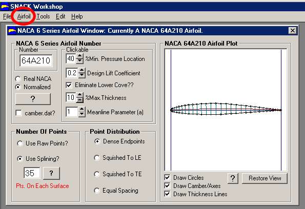
SNACK NACA 6 Series airoil generation window
- Using the "clickable" geometery commands, change the geometry options for the airfoil you desire, the
NACA 64A210 in this example:
%Min Pressure Location = 40%
Design Lift Coefficient = 0.2
Eliminate Lower Cove = checked
%Max Thickness = 10%
While the Meanline Parameter (a) is an important value in defining the geometry, it is not
specified in this case, so we will assume that it is equal to 1
- Note that the airfoil number should now read 64A210 and the plot adjusts to the proper coordinates.
If you like, you can also use the Number of Points and the Point Distribution to obtain more
accurate coordinates for your application.
- To actually see the coordinates, we need to export them in some format that can be read by another
program. To do so, select 'File' from the menu bar and 'Save As...' and the following window will
appear.
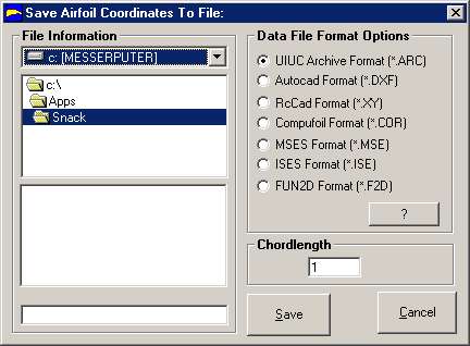
Saving airfoil coordinates from SNACK
- These file formats correspond to several airfoil aerodynamic analysis codes or CAD programs. If you
wish to utilize your coordinates in one of these applications, select the appropriate bullet. If
you simply want the coordinates, it makes little difference what format you choose, but I recommend
RcCad (*.xy). You can then open this file with a text editor or a spreadheet program for further
use. This format saves two columns of data corresponding to values of x (length) that start at the
trailing edge (x=1) and go to the leading edge (x=0) along the upper surface (y greather than 0)
and then repeats the process going back from the nose to the tail along the lower surface (y less
than 0), y being the airfoil thickness above and below the x-axis.
- The Save As... window also gives us the option of specifying an airfoil chord length. What this will
do is scale the airfoil coordinates up (if entering a number greater than 1) or down (if entering
a number less than 1) to match a desired case. For example, if we were generating the root
airfoil section for an aircraft with a root chord length of 10 feet, we would enter 10.
Nevertheless, I recommend leaving the chord at 1 to produce a generic set of coordinates. You can
always scale the values yourself later on using a program like Microsoft Excel.
- One limitation of SNACK is that it does not allow us to add the small thickness modifications called
for in the F-111 airfoils (i.e. 10.68% and 9.80%). As with adjusting the chord length, you can add
this small additional amount of thickness yourself in a spreadheet program by simply scaling the
y-coordinates up or down.
If you'd like to learn more about the mathematics of computing NACA airfoil coordinates, check out a NASA report,
TM-4741,
that covers each series. The report was written to explain the development of a
NACA airfoil generator code that is available for sale
from Public Domain Aeronautical Software (PDAS).
- answer by Jeff Scott, 17 February 2002
Related Topics:
Read More Articles:


