|
||||||||||
|
|
||||||||||
|
||||||||||
|
|
||||||||||
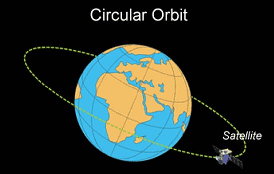
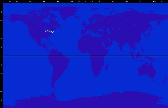
In this example, the orbit is directly above the equator. If we were to plot the path of the vehicle along the surface of the Earth, called the ground track, it would also pass directly along the equator. The following ground track for such an orbit is illustrated upon a mercator projection map of the Earth as is typically done on the displays in mission control rooms.
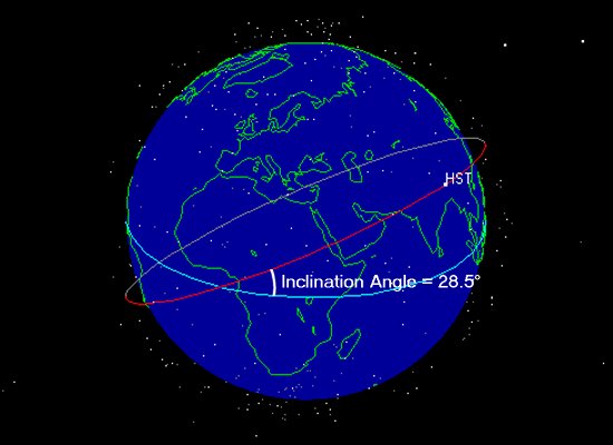
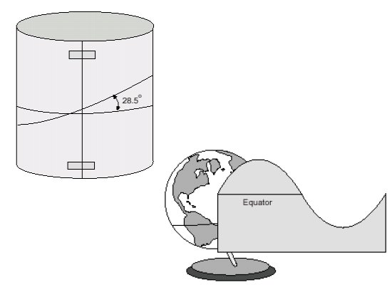
This kind of orbit is not very common on Earth since most spaecraft are launched from locations away from the equator. The majority of American satellites and manned spacecraft, for example, are launched from Cape Canaveral in Florida. Cape Canaveral is located at a latitude of 28.5° North. Since an orbit must be concentric with the center of the Earth, the orbit of a vehicle launched from such a location becomes inclined with respect to the equator. This angle is referred to as the inclination angle of the orbit. Spacecraft launched from Cape Canaveral are often placed into an orbit with an inclination of about 28.5°. Good examples of this type of orbit include the Space Shuttle and the Hubble Space Telescope (HST). The three-dimensional orbit of the HST is shown below.
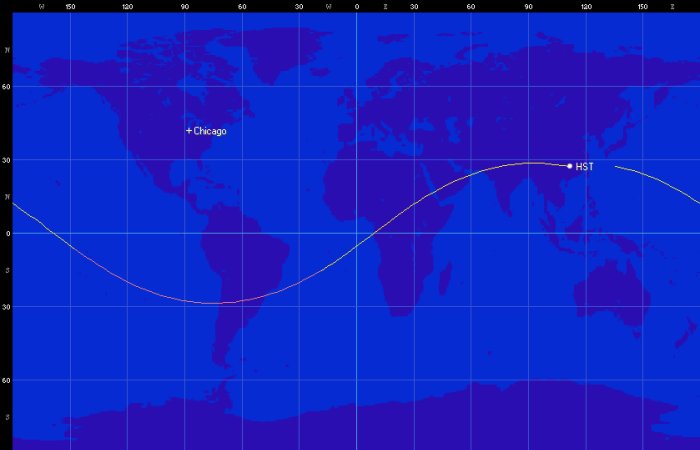
Since the three-dimensional orbit of the HST is inclined at an angle to the equator, its ground track upon a two-dimensional map also crosses north and south of the equator. Drawing this three-dimensional circular orbit on a two-dimensional map results in the periodic sinusoidal shape referred to in the question. The corresponding ground track for the HST is pictured below.
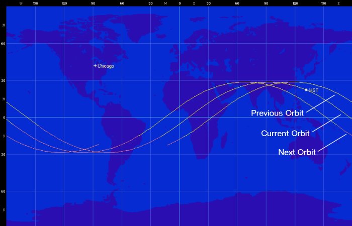
However, the ground track of many satellites typically changes from orbit to orbit. The reason for this behavior is that most satellites travel around the planet at a different speed than the Earth rotates around its axis. The HST is in a Low Earth Orbit (LEO) and completes an orbit in just 96 minutes whereas it takes the Earth 24 hours (1,440 minutes) to complete a rotation. Since the HST orbits the planet much faster than the Earth rotates, the telescope circles the Earth about 15 times per day and each orbit moves further across the surface of the Earth than the one before. In other words, the HST is never over the same point on the surface of the Earth when it is at the same position in its orbit. This behavior produces a series of orbits whose ground tracks move across the surface of the Earth. The following example illustrates a ground track showing where HST was over its previous orbit, where it is now, and where it will be over its next orbit.
Over time, a vehicle in this type of orbit will cover most of the surface of the Earth. NASA has taken advantage of this phenomenon in the past to conduct mapping or survey missions over the planet. One example was a laser altimeter experiment carried aboard the Space Shuttle that produced a highly accurate elevation map of the planet. The laser altimeter was operated over numerous orbits resulting in the following ground track map from the mission.

To better understand why circular orbits produce these sine-wave ground tracks, you can also try a simple experiment yourselves. Take a regular sheet of paper and roll it into a cylindrical tube. Though the tube is obviously not a sphere like the Earth, the principle is the same. Now using a black marker, draw a circle on the surface of the cylinder, inclined by some amount relative to the short axes of the cylinder. What you have drawn is a circular, inclined "orbit" in 3-dimensional space. Now unroll the tube and lay it flat. You will see that your circle in 3-dimensional space has been transformed into a sine wave in 2-dimensional space.
Another great way to explore the relationship between orbits and ground tracks is through software available on the internet. Most of the illustrations shown in this article were created using two pieces of free software. The first is NASA's J-Track and J-Track 3D. These java applets allow the user to plot two-dimensional ground tracks or three-dimensional orbits for any of a vast number of satellites in Earth orbit.
Another great free tool is the Orbitron Satellite Tracking System
developed by Sebastian Stoff. Orbitron works similarly to the NASA applets but can be installed as an executable
or screen saver and offers a powerful interface. Orbitron can be customized to display numerous satellites,
different types of ground tracks and footprints, various world maps, and orbital parameters.
- answer by Aaron Brown, 6 August 2006
Related Topics:
Read More Articles:


|
Aircraft | Design | Ask Us | Shop | Search |
|
|
| About Us | Contact Us | Copyright © 1997- | |||
|
|
|||
