|
||||||||||
|
|
||||||||||
|
||||||||||
|
|
||||||||||
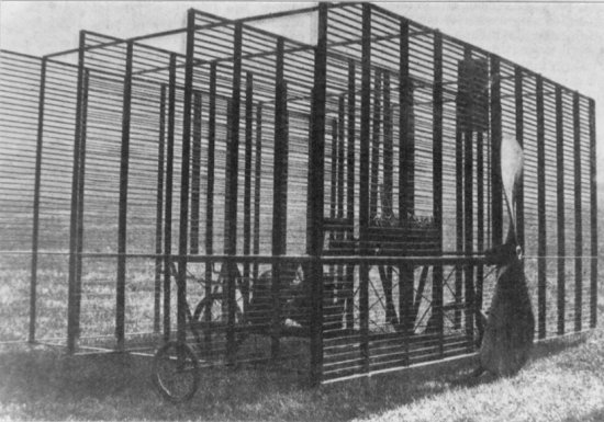
This picture is indeed of a real airplane called the Phillips Multiplane of 1907. Designed and built by Horatio Phillips of Britain, this aircraft was his third and final Multiplane featuring literally 200 separate wings! Amazingly, the 1907 Multiplane did manage to become airborne briefly and completed the first successful flight by a powered heavier-than-air aircraft in the United Kingdom. Otherwise, Phillips is much better known for his contributions to the field of airfoil design where his developments were critical to the successful evolution of flight.
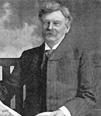
The son of a gunsmith, Horatio Phillips was born in 1845 in a suburb of London. He reportedly became interested in aviation at a young age and closely followed the research being conducted by the Royal Aeronautical Society using a whirling arm and wind tunnel. One of the leaders of the Aeronautical Society was Francis Wenham who gave an important report on the findings of his wind tunnel experiments using flat plates in 1872. In attendance at this presentation was an eager 27 year-old named Horatio Phillips who was not very impressed with Wenham's results. Nor was Phillips impressed six years later by the findings of two other Society members who expanded on Wenham's research using a large whirling arm.
Phillips felt he could do better and had built his own wind tunnel by the early 1880s. His wind tunnel used a steam injector to suck air through the apparatus and produced more reliable results than any other wind tunnel of the day. Phillips soon began conducting experiments exploring how curved airfoil sections generated lift. Basing his curved airfoils on the shape of bird wings, he called his devices the "Phillips entry" or "blades for deflecting air." These experiments were the first to conclusively prove that a cambered shape with greater curvature over the top than the bottom produced more lift than a flat airfoil. Fellow Englishman Sir George Cayley had first theorized this idea in the early 1800s, but it was the experiments of Horatio Phillips that brought widespread attention to curved airfoils. Phillips received patents on the curved shapes that he called "double-surface airfoils" in 1884 and 1891.
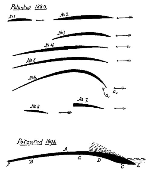
The 1891 patent detailed how a curved airfoil works since air flowing over the curved upper surface causes the air to increase in speed and decrease in pressure. The flow traveling over the lower surface remains at a lower speed and higher pressure. This difference in pressure creates a force pulling the airfoil upward, a force known as lift. This explanation formed the basis of what we today call the Bernoulli theory of lift. The following is a quote from the 1891 patent describing the above figure:
The particles of air struck by the convex upper surface 4 at the point E are deflected upward, as indicated by the dotted lines, thereby causing a partial vacuum over the greater portion of the upper surface. The particles of air under the point E follow the lower convex and concave surface C D until they arrive at about the point G, where they are brought to rest. From this point G the particles of air are gradually put into motion in a downward direction, the motion being an accelerating one until the after edge F of the blade is passed. In this way a greater pressure than the atmospheric pressure is produced on the under surface of the blade.The importance of these landmark findings was quickly recognized and nearly every subsequent experimenter with gliders or powered airplanes adopted cambered airfoils. Among these inventors were Otto Lilienthal in Germany as well as Samuel Langley and the Wright brothers in America. Phillips too applied his expertise in airfoils as he began building flying machines of his own. His first attempt came in 1893 when Phillips completed a remarkable contraption to put his curved airfoil theories into practice. Known simply as the Phillips Flying Machine, the test rig consisted of a long, slender, cigar-shaped fuselage with a frame for 50 narrow wings called "sustainers" mounted above.
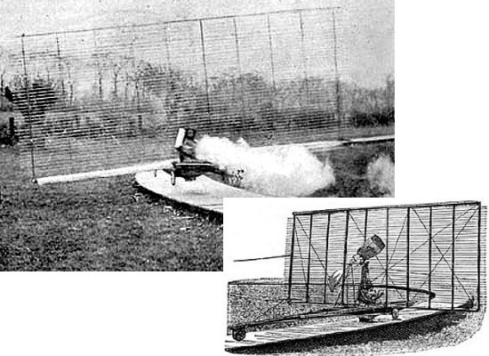
These wings, resembling the slats in a venetian blind, were set 2 inches (5 cm) apart and had a span between 19 and 22 ft (5.8 to 6.7 m) but a chord length of only 1˝ inches (3.8 cm). That design equates to an aspect ratio of at least 152! The machine sitting on a three-wheeled undercarriage was about 22 ft (6.7 m) in length and 9.5 ft (2.9 m) high with power provided by a 6-hp coal-fired steam engine driving a two-bladed propeller. The unmanned craft weighed about 350 lb (160 kg) and could reach a top speed of 40 mph (65 km/h).
In an unusual decision probably inspired by the whirling arm, Phillips chose to test his flying machine by tethering the rig to a pole and driving it along a circular track 200 ft (61 m) in diameter. The machine soon proved it could to lift a maximum weight of about 400 lb (180 kg) and also demonstrated tethered flights at an altitude of 2 to 3 ft (0.6 to 0.9 m) over a maximum distance of 2,000 ft (610 m) at lower weights. Although the Flying Machine was found to be unstable, its lifting capabilities convinced Phillips that his curved airfoil approach was sound.
Phillips next attempted a manned version of his concept and completed a Multiplane with 20 wings in 1904. This model also added a cross-shaped tail control surface for improved stability and was powered by a 22-hp four-cylinder water-cooled in-line engine that Phillips built himself. The 1904 Multiplane was 9.75 ft (3 m) in length, 10 ft (3 m) tall, and weighed about 600 lb (270 kg) with the pilot. Built of spruce, ash, and steel tubing with a calico fabric covering, the craft could reach a speed of 34 mph (55 km/h). Phillips managed to take the Multiplane on at least one short hop covering about 50 ft (15 m) in distance, but longitudinal stability remained inadequate.
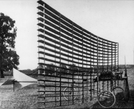
Horatio Phillips set out to correct the deficiencies of his earlier aircraft with a final attempt known as the 1907 Multiplane. This design returned to the earlier Flying Machine concept with 50 individual wings mounted atop one another in a single bank. This bank was then repeated to produce four sets of wings in a large cage structure for a total of 200 lifting elements! The 1907 Multiplane was also built of wood and powered by a 22-hp engine, similar to that of his 1904 Multiplane, driving a 7 or 8 ft (2.1 to 2.4 m) diameter propeller. Weighing about 500 lb (225 kg) without a pilot, the aircraft was designed to lift off at a speed of 30 mph (48 km/h).
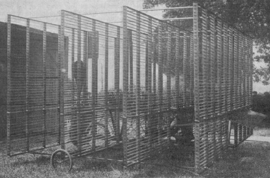
Phillips successfully flew the 1907 Multiplane over a distance of approximately 500 ft (150 m) on 6 April 1907, which some believe is the first successful powered flight in the United Kingdom. Others disagree on the grounds that the Multiplane was not controllable and could not complete a true flight. Regardless, this success apparently marked the end of Phillips' flying career since he disappeared from the aeronautics field after 1908.
Had he instead applied his knowledge of airfoils to more conventional biplane or monoplane designs, Phillips might
have become one of the most well renowned aircraft designers of his day. Unfortunately, he appears to have gone
overboard with his love of airfoils and became obsessed with Multiplanes that could never be practical machines
even if they did work. Horatio Phillips passed away in 1924 and was able to witness the rapid advances in aviation
that occurred during and after World War I. Perhaps he took comfort in the knowledge that his research into
cambered airfoils had made much of it possible.
- answer by Joe Yoon, 12 June 2005
Related Topics:
Read More Articles:


|
Aircraft | Design | Ask Us | Shop | Search |
|
|
| About Us | Contact Us | Copyright © 1997- | |||
|
|
|||
