|
||||||||||
|
|
||||||||||
|
||||||||||
|
|
||||||||||
|
|
|
||||||||||||
|
Non-Articulated Rotors:To begin a discussion of a helicopter rotor in forward flight, it is first necessary to consider a non-articulated rotor. A rotor disk viewed from above is depicted below. In this example figure, the helicopter is traveling at a forward velocity V of 130 mph (210 km/h), and the rotor has a rotational speed of Ω and a blade tip velocity of 420 mph (675 km/h). As is the convention in Western countries, the rotor is rotating in a counter-clockwise direction.
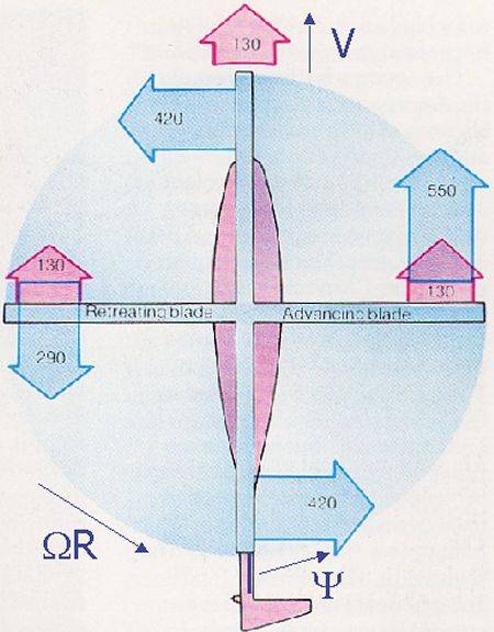
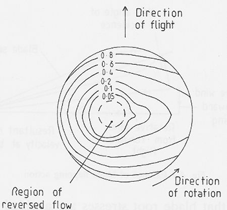
Velocities of rotor in forward flight [from Gunston and Spick, 1986]The advance ratio, denoted as μ, is equal to V/ΩR, and it usually has a value between 0 and 0.5. The azimuth angle of a blade is denoted as Ψ, where Ψ=0° at the downstream position. With this definition, advancing blades have Ψ=0° to 180°, while retreating blades have Ψ=180° to 360°. As can be seen in the above figure, the maximum and minimum velocities for the blades occur at Ψ=90° and Ψ=270°, respectively. If the blades were to rotate at a fixed incidence, then this velocity differential would cause four-fifths of the total lift of the rotor to be created on the advancing side. The calculated pressure contours for a fixed incidence rotor with an advance ratio of μ=0.3 are shown below.

Calculated pressure contours for fixed blade incidence [from Seddon, 1990]Obviously, this large imbalance of force on the rotor would lead to large oscillatory stresses at the blade roots, along with a large rolling moment. This would make the helicopter very unflyable, both from a dynamics and structural viewpoint. Articulated Rotors:To reduce this large force differential, a cyclical variation of the blade incidence is needed. The most common way of reducing the blade incidence is with flapping hinges, which were first used by Cierva in 1923, as discussed in a previous section on historical developments. When using flapping hinges, the blade is hinged as close as possible to its root, allowing the entire blade to "flap" up and down as it rotates.
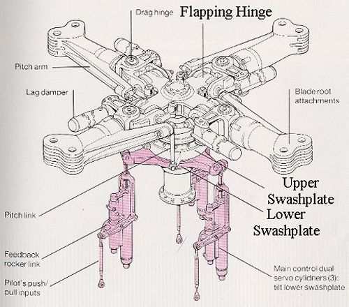
An articulated rotor hub [from Gunston and Spick, 1986]When a blade is on the advancing side, its increased lift causes the blade to flap upwards, which effectively reduces its incidence. The opposite occurs on the retreating side. Due to the presence of the flapping hinges, none of the bending forces or rolling moments is transferred to the helicopter body. Centrifugal force is typically enough to prevent the blades from flapping to a large degree, but many helicopters also employ stops as an added preventative measure. The use of flapping hinges also creates a better force balance on the rotor, distributing the lift more evenly. Calculated pressure contours for a variable incidence rotor can be seen below.
Calculated pressure contours for variable incidence [from Seddon, 1990]
|


|
Aircraft | Design | Ask Us | Shop | Search |
|
|
| About Us | Contact Us | Copyright © 1997- | |||
|
|
|||
