|
||||||||||
|
|
||||||||||
|
||||||||||
|
|
||||||||||
|
|
|
||||||||||
|
Before detailing the specifics of waverider design and performance, we will first look at the characteristics of
and design issues related to hypersonic aircraft in general. Based on these generic results, we will see how
waveriders represent optimum shapes that maximize overall performance.
Configuration:As previously mentioned, the infinitely thin flat plate represents the most efficient hypersonic lifting surface. The lift-to-drag ratio of the flat plate is the highest that can be achieved at hypersonic speeds. However, the flat plate is obviously not practical, especially since it cannot contain any volume for payload, engines, fuel, etc. The figure below illustrates a more realistic design that is typical of hypersonic aircraft configurations.
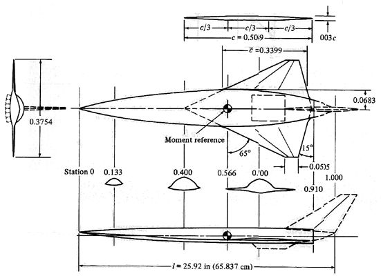
Generic hypersonic transport configuration tested by NASA [from Anderson, 2000]Note the following general characteristics of these designs:
General Aerodynamic Performance:The wind-tunnel tests conducted on the vehicle shown above indicate that the design is capable of a maximum lift-to-drag ratio of about 5.5 at an angle of attack of about 4°. These results agree well with those derived from Newtonian theory. However, these results also make it clear that hypersonic vehicles are capable of L/D ratios far below those typical of subsonic and low supersonic aircraft. For example, maximum L/D values on the order of 12 to 15 are common for designs like the P-51 Mustang fighter and F-111 bomber. Other studies of hypersonic designs have shown similar results leading to the conclusion that maximum L/D decreases as Mach number increases. Kuchemann analyzed this trend and formulated the general empirical relationship:
This relationship, based on actual data from flight vehicle and wind tunnel results, has proven generally accurate across the supersonic and hypersonic regimes. Kuchemann's equation is co-plotted below (solid line) along with a series of actual results for conventional hypersonic vehicles (open circles).
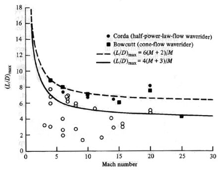
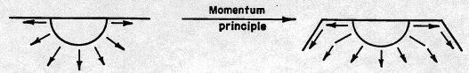
Maximum lift-to-drag ratios for hypersonic vehicles and the "L/D barrier" [from Anderson, 2000]Note that most of the open circles fall below the solid curve leading many to refer to the curve as a "L/D barrier." The conclusion to be drawn from this figure is that high L/D ratios are very difficult to achieve at high Mach numbers. This poor performance can be attributed to the strong viscous effects (high skin friction drag) and strong shock waves (high wave drag) that vehicles suffer at these high speeds. Obviously, this result is discouraging since aircraft range in steady level cruise flight is directly dependent on L/D, probably the greatest measure of "aerodynamic efficiency." The dashed curve and solid symbols shown below represent current research efforts aimed at breaking the L/D barrier. Compression Lift:Since we have seen that high L/D ratios are difficult to achieve at hypersonic speeds, how can vehicle shape be optimized to break the L/D barrier? This problem was first approached using elementary momentum principles. First, consider that an ideal hypersonic shape might be a slender body of revolution of continuously increasing radius, or a cone shape. As with any shape, the cone generates lift by imparting a change in momentum on the fluid it passes through. In other words, the body generates a downward force on the fluid and the fluid generates an upward force on the body by Newton's third law of motion. The L/D of the body is maximized when it maximizes the downward momentum and minimizes the forward momentum imparted on the surrounding fluid. However, since a body of revolution imparts upward momentum as well as downward, the pressure forces acting on each surface cancel. This can be thought of as generating a positive lift on the lower surface and a negative lift on the upper surface. This so-called momentum principle therefore dictates that the upper half of the body of revolution should be eliminated resulting in the shape shown below:
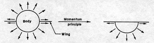
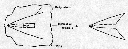
Derivation of hypersonic body shape using momentum principle [from Eggers and Syvertson, 1956]Next, consider the shape of the wing. The figure below illustrates a top view of the body of revolution derived in above attached to some arbitrary wing shape. As the body passes through a high-speed flowfield, it generates a shock wave, and the body can only impart downward momentum on the fluid between its surface and the shock wave. Thus, the wing should extend to the shock wave to capture this change in momentum but not beyond it since this extra area will only create more skin friction drag and structural weight.
Derivation of hypersonic wing shape using momentum principle [from Eggers and Syvertson, 1956]Returning to the front view of the body previously discussed, recall that the body not only imparts downward momentum on the fluid but also a lateral, or sideways, component. If this lateral momentum could also be deflected downward, lift could be further increased. A method of accomplishing this is through the use of tip flaps, or wing tips that deflect downward about a hinge line parallel to the flow direction.
Derivation of hypersonic wing tip shape using momentum principle [from Eggers and Syvertson, 1956]Application of the elementary momentum principle produces an aircraft configuration like that illustrated below.
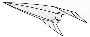
Complete hypersonic vehicle shape derived using momentum principle [from Eggers and Syvertson, 1956]Note that despite the crude appearance of the above configuration, this method was used to design a successfully flight-tested Mach 3 aircraft that will be discussed later. These so-called "flat-top" wings were tested in the wind tunnel at speeds ranging from Mach 3 to 6. It was found that although the maximum L/D decreased slightly as the tip flap deflection increased (due to decreasing lift-curve slope), L/D at low angles of attack increased for a given angle of attack, as shown below.
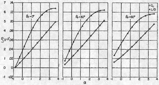
Lift coefficient and L/D ratios with increasing tip flap deflection at M=3.0 [from Eggers and Syvertson, 1956]Although the authors of this study did not describe their findings as such, they had stumbled upon the basic design criteria that would come to be applied to waveriders. The increase in lift they attributed to momentum principles would soon come to be better understood as compression lift. Compression lift is that lift that is gained because of the increase in surface pressure realized on the underside of a hypersonic vehicle due to the close proximity of the thin shock layer. The concept of matching the wing leading edge to the shock formed off the vehicle forebody is the underlying principle behind the waverider concept. Stability and Control:Because of the fundamental differences between subsonic and hypersonic design criteria, we might expect fundamental differences in the stability and controllability of aircraft flying in these conditions. Indeed, this is the case and much research is being conducted to determine the optimum methods of trimming and controlling a hypersonic vehicle across its speed range. One such research vehicle, LoFlyte, will be discussed later. Most hypersonic vehicles have been designed with rudders and combined elevator-ailerons (or elevons) as primary control surfaces. Another feature often used is the tip flap, discussed previously, which not only improves lift but also contributes to rudder effectiveness. A combination of ailerons and tip flaps is sometimes referred to as tiperons. In general, hypersonic vehicles incorporating these control surfaces have been found to exhibit adequate stability characteristics at both cruise and takeoff/landing conditions. However, the overall vehicle design, especially the outer portion of the wing, plays a significant roll in stability and control behavior. For example, the vehicle shown below was wind-tunnel tested with both a straight wing and a cranked wing, or a wing in which the dihedral changes towards the tip.
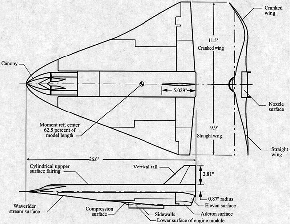
Hypersonic waverider concept designed using conical-flow techniques and using both straight and cranked wing panels to compare stability and control characteristics [from Cockrell and Huebner, 1995]Results showed that the while the ailerons on the straight wing provided much greater roll control and less adverse yaw, the cranked wing provided improved lateral-directional stability. Both designs were found to be longitudinally unstable indicating that a hypersonic vehicle will likely need a fly-by-wire control system, a fuel control system, or careful vehicle packaging to maintain trim. Propulsion Integration:Subsonic aircraft typically feature engine mountings that are distinct components by themselves. For example, the engine pods of the Boeing 747 are easily identifiable. Even designs intended for low-supersonic speeds, like the Concorde, feature distinct engine pods. This will almost surely not be the case in any hypersonic air-breathing design. Since thin shock layers are so common in hypersonic flight, designers must be careful to prevent the shock wave from one component of the aircraft from adversely interfering with another component. In addition, a hypersonic vehicle will likely utilize some kind of ramjet or scramjet engine. These engines are similar to turbojets except they dispense with the compressor and turbine stages. Instead, these engines rely on the motion of the vehicle itself to compress the incoming flow before combustion occurs. The specific details of ramjet and scramjet operation are beyond the scope of this paper, but readers are referred to Oates, 1988, Hill and Peterson, 1992, and Siuru and Busick, 1994 for more information. Suffice it to say that shock interactions and ideal engine operation dictate that the propulsion system be highly integrated into the overall airframe design. An example, shown below, illustrates how a scramjet engine would likely be incorporated into a hypersonic vehicle.
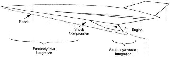
Engine/airframe integration on a hypersonic vehicle [from Hallion, vol. 2, 1998]Note how the engine package is placed to take advantage of the shock generated by the vehicle forebody. The flow is compressed behind the shock increasing the pressure within the engine so that it will produce greater thrust as a result. In addition, the aft portion of the vehicle is designed to promote expansion of the exhaust so that it is actually an extension of the scramjet nozzle. Thus, the entire undersurface of the vehicle can be considered to be part of the propulsion system. The X-30 and Hyper-X both utilize this engine integration concept.
Heat Transfer Issues:Any hypersonic vehicle will spend the majority of its cruise flight in very high temperature flows. As a result, the designer must pay close attention to temperatures on various portions of the vehicle to ensure that structures and materials will not fail at these conditions. Aerodynamic issues lead the designer to very sharp leading edge surfaces to minimize drag, but heat transfer issues require blunted shapes to spread heat flux over a larger area and to provide volume for the application of heat absorbing or ablative materials. This conflict can be alleviated to some degree using cryogenic cooling systems to pump low temperature fluids through the vehicle structure, especially along leading edges. The vehicle need not carry a special, additional fluid for this system since hypersonic vehicles will likely be fueled by liquid hydrogen or some other cryogenically cooled liquid. The technique of pumping fuel through the vehicle structure was successfully used on the B-70 Mach 3 bomber and was also proposed for the X-30 research vehicle. A hypersonic vehicle will also likely require some kind of heat-resistant flexible coating, like that of the SR-71 Blackbird and Space Shuttle. |


|
Aircraft | Design | Ask Us | Shop | Search |
|
|
| About Us | Contact Us | Copyright © 1997-2023 | |||
|
|
|||
