|
||||||||||
|
|
||||||||||
|
||||||||||
|
|
||||||||||
 - -
|
|
|
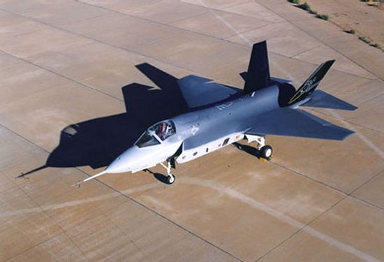
Lockheed Martin X-35 Fighter Demontrator |
|
DESCRIPTION:
As part of the Joint Strike Fighter project, Lockheed Martin was funded to build the X-35 demonstrator to compete against the Boeing X-32. The winner of this competition would receive a major contract to develop a production fighter for the US Air Force, US Navy, US Marine Corps, and UK Royal Navy. Lockheed was joined by partners Northrop Grumman and British Aerospace in developing an aircraft resembling the larger F-22. The X-35 was powered by an advanced engine derived from that used on the F-22 and fed by two side intakes mounted beneath swept wings. To meet the needs of the various services, three variants of the X-35 were designed and test flown between 2000 and 2001. The conventional takeoff and landing (CTOL) X-35A was developed for the US Air Force, the short takeoff and vertical landing (STOVL) X-35B for the US Marines and UK Royal Navy, and the carrier-based (CV) X-35C for the US Navy. However, Lockheed was actually only funded to construct two prototypes for evaluation. The X-35A, first to be completed, was used for early flights before being modified and fitted with a second engine. This additional engine, a shaft-driven lift-fan system plus roll control jets along the wings, was coupled to the primary engine to provide the lift for vertical flight. This modified airframe was redesignated the X-35B for completion of the STOVL portion of the evaluation process. During the three-month conversion process, test flight duties were assumed by the X-35C demonstrator for the Navy. This model featured an enlarged wing of greater span and area for larger fuel capacity. The X-35C was also equipped with enlarged horizontal tails and flaperons for greater control effectiveness during low-speed carrier approaches. Once the conversion of the X-35A to the X-35B was complete, Lockheed proceeded with the most challenging portion of the flight test demonstration effort. The use of two separate engines to meet the vertical flight requirement was inspired by the Russian Yak-141. The additional lift fan fitted to the X-35B was powered by the F119 engine but provided an independent source of thrust in hover mode. While the hover method adopted by Boeing in the X-32 was considered more conventional, Lockheed argued that the lift fan approach offered more room for growth in aircraft's future design evolution. The US military appeared to agree with Lockheed Martin's argument in October 2001 when the company was selected to proceed with the development of a production F-35 fighter.
Data below for X-35A |
|
| HISTORY: | |
| First Flight |
(X-35A) 24 October 2000 (X-35B) 23 June 2001 (X-35C) 16 December 2000 |
|
Service Entry
|
see F-35
|
| CREW: |
one: pilot
|
|
ESTIMATED COST:
|
(X-35A) $28 million [1994$] (X-35B) $35 million [1994$] (X-35C) $38 million [1994$] |
| AIRFOIL SECTIONS: | |
| Wing Root | unknown |
|
Wing Tip
|
unknown
|
| DIMENSIONS: | |
| Length |
(X-35A) 50.50 ft (15.41 m) (X-35C) 50.80 ft (15.50 m) |
| Wingspan |
(X-35A) 32.78 ft (10.00 m) (X-35C) 43.00 ft (13.12 m) (X-35C) 29.83 ft (9.10 m) folded |
| Height | unknown |
| Wing Area |
(X-35A) 450 ft˛ (41.8 m˛) (X-35C) 540 ft˛ (50.2 m˛) |
|
Canard Area
|
not applicable
|
| WEIGHTS: | |
| Empty |
(X-35A/C) about 22,000 lb (9,980 kg) (X-35B) about 23,500 lb (10,660 kg) |
| Normal Takeoff | unknown |
| Max Takeoff | about 50,000 lb (22,680 kg) |
| Fuel Capacity |
internal: unknown external: unknown |
|
Max Payload
|
about 15,000 lb (6,805 kg)
|
| PROPULSION: | |
| Powerplant |
(X-35A/C) one Pratt & Whitney F119-611 turbofan (X-35B) one Pratt & Whitney F119-611 turbofan and one Rolls-Royce/Allison shaft-driven lift-fan |
| Thrust |
(PW) about 35,000 lb (155 kN) (RR) about 18,000 lb (80 kN) |
| PERFORMANCE: | |
| Max Level Speed |
at altitude: about Mach 1.5 at sea level: unknown |
| Initial Climb Rate | unknown, but similar to F-16 |
| Service Ceiling | unknown |
| Range |
(X-35B) 1,080 nm (2,000 km) (X-35C) 1,620 nm (3,000 km) |
| Endurance | unknown |
| g-Limits |
unknown
|
| KNOWN VARIANTS: | |
| X-35A | Experimental multi-role conventional takeoff (CTOL) fighter for the US Air Force, recorded 27.4 flight hours in 27 flights from 24 October 2000 to 22 November 2000 achieving a maximum speed of Mach 1.05, a maximum altitude of 34,000 ft (10,360 m), and +5g loading; 1 built |
| X-35B | Experimental multi-role short takeoff and vertical landing (STOVL) fighter for the US Marine Corps and UK Royal Navy equipped with a lift fan in place of a fuel tank; the X-35A was converted into the X-35B for STOVL tests completing 21.5 hours of flight time in 39 flights (17 vertical take-offs, four short take-offs, six short landings, 27 vertical landings) from 23 June 2001 and 30 July 2001 |
| X-35C | Experimental navalized (CV) fighter similar to the X-35A but with larger wings for increased fuel capacity as well as larger horizontal tails and control surfaces, recorded 58 hours of flight time in 73 flights from 16 December 2000 and 10 March 2001 achieving a maximum speed of Mach 1.22 and completing over 250 simulated carrier landings; 1 built |
| F-35 |
Production fighter
|
|
KNOWN OPERATORS:
|
United Kingdom (Royal Navy) United States (US Air Force) United States (US Marine Corps) United States (US Navy) |
|
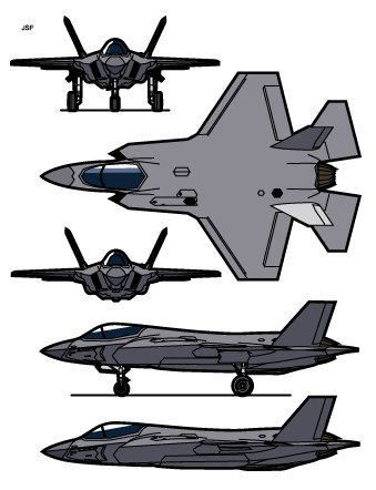
3-VIEW SCHEMATIC:
|
|
SOURCES:
|
|


|
Aircraft | Design | Ask Us | Shop | Search |
|
|
| About Us | Contact Us | Copyright © 1997- | |||
|
|
|||
